
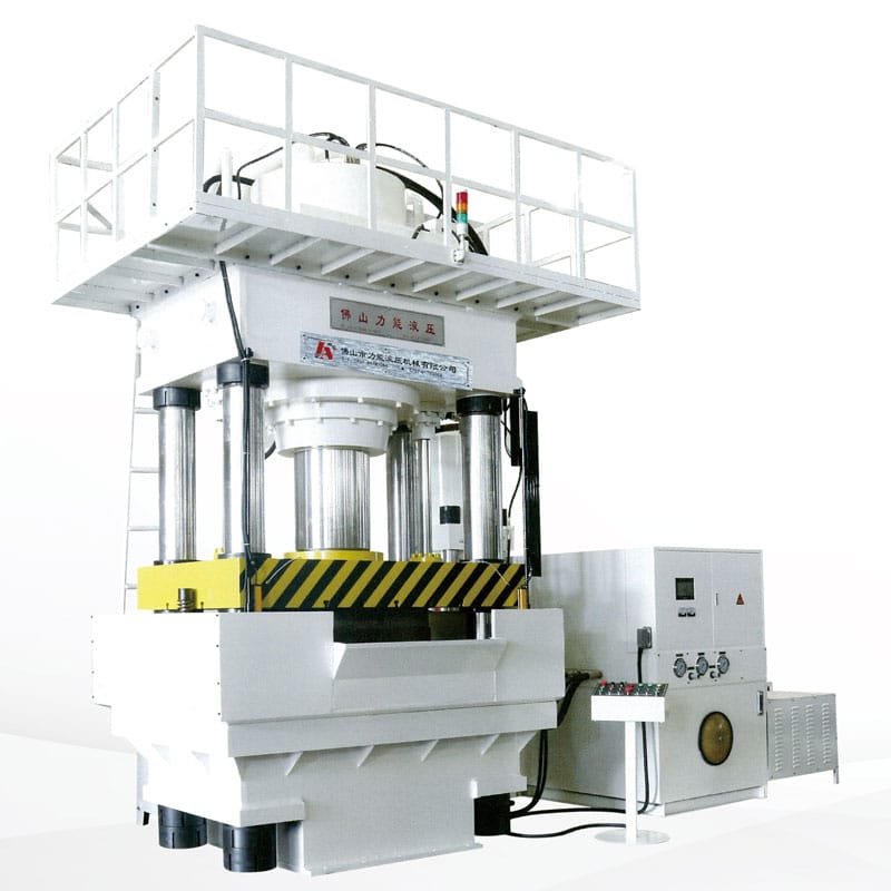
LN99 series internal high-pressure forming hydraulic press
brief introduction:Internal high-pressure forming is an advanced light weight for ming technology that presses the tube blank into the mold cavity by applying pressure and axial force to supplement the material.
Product Category

Product Feature
- The movable crossbeam has two sections of speed, fast descending without load, slow profiling and pressing, fast return, and high work efficiency;
- Automatic counting function;
- The main sealing components are imported products, with a long service life;
- The key electrical components adopt well-known brands from Europe, America, and Japan, with high working reliability;
- The hydraulic components are selected from internationally renowned brands to ensure good performance;
- The surface of the column and piston rod are treated with medium frequency and plated with hard chromium;
- Equipped with infrared protection device for safer operation;
- Centralized lubrication system to extend the service life of the machine:
- Multiple working modes: the main cylinder has fixed stroke and constant pressure options, the side cylinder can be used separately, simultaneously, or not, and the booster cylinder can be used or not;
- High work pressure, clear forming texture;
- The hydraulic system adopts a two way plug-in valve control, with small pressure loss and stable and reliable action.
Process Characteristics
- Reduce quality and save materials;
- Reduce the number of parts and molds, reduce mold costs, and usually only one set of molds is required for internal high-pressure components;
- Can reduce the amount of subsequent mechanical processing and assembly welding;
- Improve strength and stiffness, especially fatigue resistance;
- Design with variable clamping force, forming parts with uniform wall thickness and minimal thinning.
Technical Parameter
| Project | Unit | Parameter | |||||
| LN99-1200 | LN99-1400 | LN99-1800 | LN99-2100 | LN99-3000 | |||
| Main cylinder nominal force | KN | 6000 | 8000 | 12000 | 15000 | 24000 | |
| Maximum working pressure of main cylinder liquid | Mpa | 24 | 24 | 24 | 25 | 25 | |
| Maximum working stroke of the clamping cylinder | mm | 500 | 500 | 500 | 600 | 800 | |
| Nominal force of side push cylinder | KN | 2000×2 | 2000×2 | 2000×2 | 2000×2 | 2000×2 | |
| Maximum working pressure liquid in side pushing cylinder | Mpa | 24 | 24 | 25 | 25 | 25 | |
| Maximum working stroke of side push cylinder | mm | 200 | 200 | 200 | 200 | 200 | |
| Maximum opening height of workbench | mm | 900 | 900 | 1000 | 1200 | 1500 | |
| Moving beam lifting speed | Quick down | mm/s | 200 | 200 | 200 | 200 | 200 |
| Industrial progress | mm/s | 15 | 12 | 10 | 6 | 5 | |
| Return journey | mm/s | 200 | 200 | 200 | 200 | 150 | |
| Maximum output pressure of booster cylinder | Mpa | 120 | 120 | 120 | 150 | 250 | |
| Booster cylinder volume | L | 7 | 7 | 7 | 6 | 5 | |
| Booster cylinder stroke | mm | 400 | 400 | 400 | 400 | 400 | |
| Effective volume of worktable | Left and right(inside the column) | mm | 1200 | 1200 | 1500 | 2000 | 2500 |
| Front and rear(edge) | mm | 1200 | 1200 | 1200 | 1400 | 1500 | |
| Motor power | KW | 45+22×2+3 | 45+22×2+3 | 30×2+22×2+3 | 37×2+22×2+3 | 45×2+37+22×2+3 | |